The MIDI controllers offered on the modern market have various functions and differ in price. To get the device you need, you can do your homework and opt for the best 25-key MIDI controller. However, the multifunctional factory devices cost quite much and are seldom fully customizable. If you wish to have a MIDI controller that fits your needs and doesn’t cost you an arm and a leg, you can make one yourself.
Don’t worry, you won’t have to plunge into microelectronics deeply and create a board, resistors, capacitors, etc. on your own. Almost any DIY MIDI controller kit is based on the Arduino board letting you skip the fine mechanics and electric science. However, it’s good to have a basic knowledge of this science so that you could define the type of board you need. Scroll down for a quick guide on building the DIY MIDI controller.
How to Make a MIDI Controller
In a few simple steps, learn how to make a MIDI keyboard.
- Determine the number and purpose of buttons, faders, and knobs. The MIDI controller can feature from 2 to multiple buttons, and implement other elements of control (mainly potentiometers). The number and purpose of controls determine the complexity of the breadboard used.
- Make a sketch of your desired MIDI controller. Take a sheet of paper of the same size the top panel of your DIY controller will be and draw each outside element, and where it should be positioned. Indicate the distance between the controls, and to the edges of the box, on your plan. Make sure to point to exactly the middle part of each button.
- Collect the necessary materials. You’ll need all control elements (buttons, potentiometers), the MIDI connector (some of the MIDI assembling kits let you build a DIY USB MIDI controller featuring a USB as well), a soldering tool, and materials. It’s better to have more buttons at hand than you plan to insert into your MIDI controller, and of different colors, to discern the buttons easily. In case you have buttons of the same color, you can paint them or write down/print the inscriptions on the paper strips, and glue them beneath the buttons. To prepare an enclosure, you’ll need panels of wood, plastic, or another type. You’ll also need a drill, a multi function tool, a saw, a file, metal brackets and screws, and glue. Choose the breadboard that’ll accommodate all the controls of your future MIDI controller. You’ll also need software for programming, integrating, and mapping your controller.
- Shape the enclosure. Prepare all the panels (top, bottom, and side ones) but don’t fix them together. Use a drill and a spade bit to make the holes for the buttons. Make sure the holes are 0.05-inch wider than the buttons so that they fit in smoothly. Apply a multi function tool to make even cuts for faders. Use a drill and a spade bit to make a hole in the rear side panel where the MIDI or USB connector will be installed. File all holes and edges so that the surfaces get polished and won’t get in the way.
- Insert all buttons and faders into their openings on the top panel, install a MIDI connector within a rear side panel. Then, refer to the circuit scheme supplied with your breadboard, and map your soldering. There’s going to be a lot of wire, so, it’s better to plan beforehand what wire to solder first.
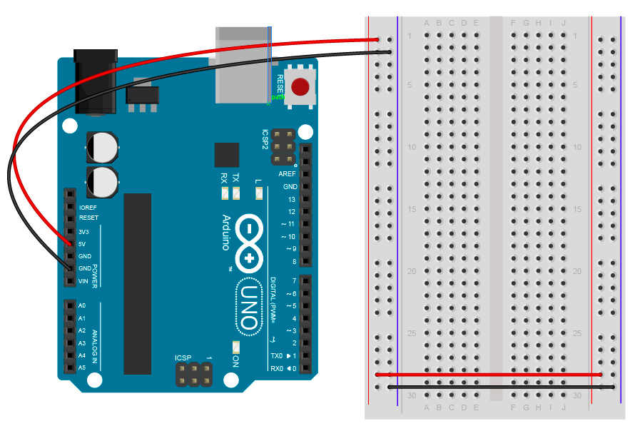
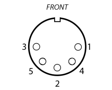
Select one pin of the button as a ground, another will serve as a power wire. For the Pot knobs, the right pin goes for power, the left one for ground, and the middle one is soldered to a signal wire. The sliding potentiometers also have three pins, where the top one goes for signal transmission, the middle one for power, and the bottom pin serves as a ground. For the MIDI connector soldering, apply the following scheme, where the 2nd pin is connected to the ground wire, the 4th pin—to the power one (via the resistor), and the 5th pin serves for the transmission of the MIDI signal (also via the resistor).
- Assemble the enclosure but don’t seal it so far. Fix the side panels with the bottom one, insert the MIDI connector into its opening. Put the breadboard inside and install the top part of the box.
- Now that the physical part of the work is over, you’ll have to do the programming. You’ll need to install the software to control your breadboard, the MIDI control software, and the DAW software to map and test the MIDI signal input and output. It’s also a good idea to install signal testing MIDI software on your PC to test the signal flow at the start. In order to install and set up the software you selected, follow the instructions that come with it or search the Internet for them. You’ll need a programming code as well. It usually isn’t difficult but can be lengthy. Thus, it’s advisable to download the ready-to-use code for specific software.
- Connect the MIDI controller to a PC via the MIDI-to-USB interface (or a USB cable, if you used the USB B port for input/output). Enter the MIDI Controller program, and choose the MIDI IN port. Now, activating the testing software, you should see the system react to the button being pressed. If there’s no reaction, perform the debugging procedure, ensure the physical connection is solid, and that the breadboard is fed with the power.
- Enter the DAW software and map the buttons and faders to your preference. Connect the speakers or use the internal speaker on your laptop, and listen to the sound created by your DIY MIDI controller. You can regulate the sensitivity of controls and program their interaction as well.
- Upon ensuring everything works as it should, you can seal the box, work out the seams so that the surfaces would be smooth, and start using your MIDI controller.

Hi everyone! I’m Thomas Moody, also known as Guitarzan.